CCNA – WAN 2
Here you will find answers to WAN Questions – Part 2
If you are not sure about Frame Relay, please read my Frame Relay tutorial.
Question 1
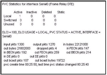
Users have been complaining that their Frame Relay connection to the corporate site is very slow. The network administrator suspects that the link is overloaded. Based on the partial output of the Router#show frame relay pvc command shown in the graphic, which output value indicates to the local router that traffic sent to the corporate site is experiencing congestion?
A. DLCI=100
B. last time PVC status changed 00:25:40
C. in BECN packets 192
D. in FECN packets 147
E. in DF packets 0
Answer: C
Explanation
First we should grasp the concept of BECN & FECN through an example:
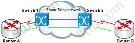
Suppose Router A wants to send data to Router B through a Frame Relay network. If the network is congested, Switch 1 (a DCE device) will set the FECN bit value of that frame to 1, indicating that frame experienced congestion in the path from source to destination. This frame is forwarded to Switch 2 and to Router B (with the FECN bit = 1).
Switch 1 knows that the network is congesting so it also sends frames back to Router A with BECN bit set to 1 to inform that path through the network is congested.
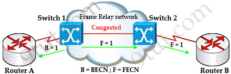
In general, BECN is used on frames traveling away from the congested area to warn source devices that congestion has occurred on that path while FECN is used to alert receiving devices if the frame experiences congestion.
BECN also informs the transmitting devices to slow down the traffic a bit until the network returns to normal state.
The question asks “which output value indicates to the local router that traffic sent to the corporate site is experiencing congestion” which means it asks about the returned parameter which indicates congestion -> BECN.
Question 2
When troubleshooting a Frame Relay connection, what is the first step when performing a loopback test?
A. Set the encapsulation of the interface to HDLC.
B. Place the CSU/DSU in local-loop mode.
C. Enable local-loop mode on the DCE Frame Relay router.
D. Verify that the encapsulation is set to Frame Relay.
Answer: A
Explanation
The first thing when performing a loopback test on a Frame Relay connection is to reconfigure the encapsulation of the interface to HDLC protocol instead of Frame Relay protocol. The main reason is Frame Relay requires a pair of DCE/DTE which cannot be used in a loopback test.
For more information about steps of trouble shooting Frame Relay, please read: http://www.cisco.com/en/US/tech/tk713/tk237/technologies_tech_note09186a008014f8a7.shtml#topic20
For your information, below is a paragraph quoted from the above link:
“Serial0 is down, line protocol is down”
This output means you have a problem with the cable, channel service unit/data service unit (CSU/DSU), or the serial line. You need to troubleshoot the problem with a loopback test. To do a loopback test, follow the steps below:
1. Set the serial line encapsulation to HDLC and keepalive to 10 seconds. To do so, issue the commands encapsulation hdlc and keepalive 10 under the serial interface.
2. Place the CSU/DSU or modem in local loop mode. If the line protocol comes up when the CSU, DSU or modem is in local loopback mode (indicated by a “line protocol is up (looped)” message), it suggests that the problem is occurring beyond the local CSU/DSU. If the status line does not change states, there is possibly a problem in the router, connecting cable, CSU/DSU or modem. In most cases, the problem is with the CSU/DSU or modem.
3. Ping your own IP address with the CSU/DSU or modem looped. There should not be any misses. An extended ping of 0x0000 is helpful in resolving line problems since a T1 or E1 derives clock from data and requires a transition every 8 bits. B8ZS ensures that. A heavy zero data pattern helps to determine if the transitions are appropriately forced on the trunk. A heavy ones pattern is used to appropriately simulate a high zero load in case there is a pair of data inverters in the path. The alternating pattern (0x5555) represents a “typical” data pattern. If your pings fail or if you get cyclic redundancy check (CRC) errors, a bit error rate tester (BERT) with an appropriate analyzer from the telco is needed.
4. When you are finished testing, make sure you return the encapsulation to Frame Relay.
Question 3
What occurs on a Frame Relay network when the CIR is exceeded?
A. All TCP traffic is marked discard eligible.
B. All UDP traffic is marked discard eligible and a BECN is sent.
C. All TCP traffic is marked discard eligible and a BECN is sent.
D. All traffic exceeding the CIR is marked discard eligible.
Answer: D
Explanation
Committed information rate (CIR): The minimum guaranteed data transfer rate agreed to by the Frame Relay switch. Frames that are sent in excess of the CIR are marked as discard eligible (DE) which means they can be dropped if the congestion occurs within the Frame Relay network.
Note: In the Frame Relay frame format, there is a bit called Discard eligible (DE) bit that is used to identify frames that are first to be dropped when the CIR is exceeded.
Question 4
What are two characteristics of Frame Relay point-to-point subinterfaces? (Choose two)
A. They create split-horizon issues.
B. They require a unique subnet within a routing domain.
C. They emulate leased lines.
D. They are ideal for full-mesh topologies.
E. They require the use of NBMA options when using OSPF.
Answer: B C
Question 5
The output of the show frame-relay pvc command shows ”PVC STATUS=INACTIVE”. What does this mean?
A. The PVC is configured correctly and is operating normally,but no data packets have been detected for more than five minutes.
B. The PVC is configured correctly, is operating normally and is no longer actively seeking the address the remote route,
C. The PVC is configured correctly, is operating normally and is waiting for interesting to trigger a call to the remote router.
D. The PVC is configured correctly on the local switch, but there is a problem on the remote end of the PVC.
E. The PVC is not configured on the switch.
Answer: D
Explanation
The PVC STATUS displays the status of the PVC. The DCE device creates and sends the report to the DTE devices. There are 4 statuses:
+ ACTIVE: the PVC is operational and can transmit data
+ INACTIVE: the connection from the local router to the switch is working, but the connection to the remote router is not available
+ DELETED: the PVC is not present and no LMI information is being received from the Frame Relay switch
+ STATIC: the Local Management Interface (LMI) mechanism on the interface is disabled (by using the “no keepalive” command). This status is rarely seen so it is ignored in some books.
Question 6
Which encapsulation type is a Frame Relay encapsulation type that is supported by Cisco routers?
A. Q933-A Annex A
B. IETF
C. ANSI Annex D
D. HDLC
Answer: B
Explanation
Cisco supports two Frame Relay encapsulation types: the Cisco encapsulation and the IETF Frame Relay encapsulation, which is in conformance with RFC 1490 and RFC 2427. The former is often used to connect two Cisco routers while the latter is used to connect a Cisco router to a non-Cisco router. You can test with your Cisco router when typing the command Router(config-if)#encapsulation frame-relay ? on a WAN link. Below is the output of this command (notice Cisco is the default encapsulation so it is not listed here, just press Enter to use it).
![]()
Note: Three LMI options are supported by Cisco routers are ansi, Cisco, and Q933a. They represent the ANSI Annex D, Cisco, and ITU Q933-A (Annex A) LMI types, respectively.
HDLC is a WAN protocol same as Frame-Relay and PPP so it is not a Frame Relay encapsulation type.
Question 7
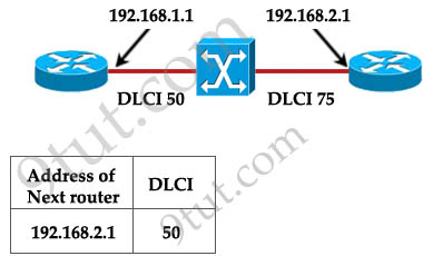
Router A is unable to reach Router B. Both routers are running ios version 12.0. After reviewing the command output and graphic, what is the most likely cause of the problem?
A. incorrect bandwidth configuration
B. incorrect LMI configuration
C. incorrect map statement
D. incorrect IP address
Answer: C
Explanation
With this topology and the DLCI, we can only think of “incorrect map statement”. From the topology we can deduce traffic with a DLCI of 75 will be sent to 192.168.2.1 but the text below wrongly shows “DLCI 50” for the next router 192.168.2.1 -> C is correct.