Cisco Router Boot Sequence Tutorial
In this article we will learn about the main components of a Cisco router and how the boot process takes place.
Types of memory
Generally Cisco routers (and switches) contain four types of memory:
Read-Only Memory (ROM): ROM stores the router’s bootstrap startup program, operating system software, and power-on diagnostic test programs (POST).
Flash Memory: Generally referred to simply as “flash”, the IOS images are held here. Flash is erasable and reprogrammable ROM. Flash memory content is retained by the router on reload.
Random-Access Memory (RAM): Stores operational information such as routing tables and the running configuration file. RAM contents are lost when the router is powered down or reloaded.
Non-volatile RAM (NVRAM): NVRAM holds the router’s startup configuration file. NVRAM contents are not lost when the router is powered down or reloaded.
Some comparisons to help you remember easier:
+ RAM is a volatile memory so contents are lost on reload, where NVRAM and Flash contents are not.
+ NVRAM holds the startup configuration file, where RAM holds the running configuration file.
+ ROM contains a bootstrap program called ROM Monitor (or ROMmon). When a router is powered on, the bootstrap runs a hardware diagnostic called POST (Power-On Self Test).
Router boot process
The following details the router boot process:
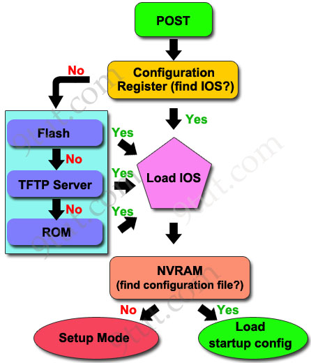
1. The router is powered on.
2. The router first runs Power-On Self Test (POST)
3. The bootstrap checks the Configuration Register value to specify where to load the IOS. By default (the default value of Configuration Register is 2102, in hexadecimal), the router first looks for “boot system” commands in startup-config file. If it finds these commands, it will run boot system commands in order they appear in startup-config to locate the IOS. If not, the IOS image is loaded from Flash . If the IOS is not found in Flash, the bootstrap can try to load the IOS from TFTP server or from ROM (mini-IOS).
4. After the IOS is found, it is loaded into RAM.
5. The IOS attempts to load the configuration file (startup-config) from NVRAM to RAM. If the startup-config is not found in NVRAM, the IOS attempts to load a configuration file from TFTP. If no TFTP server responds, the router enters Setup Mode (Initial Configuration Mode).
And this is the process we can see on our screen when the router is turned on:
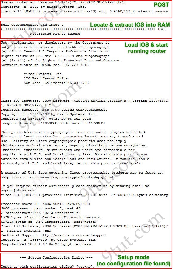
In short, when powered on the router needs to do:
1. Run POST to check hardware
2. Search for a valid IOS (the Operating System of the router)
3. Search for a configuration file (all the configurations applied to this router)
Specify how much RAM, NVRAM and Flash of a router
Also, from the information shown above, we can learn some information about router’s model, RAM, Flash, NVRAM memories as shown below:
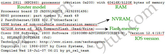
Note: The “show version” command also gives us this information.
All the above information is straight-forwarding except the information of RAM. In some series of routers, the RAM information is displayed by 2 parameters (in this case 60416K/5120K). The first parameter indicates how much RAM is in the router while the second parameter (5120K) indicates how much DRAM is being used for Packet memory. Packet memory is used for buffering packets.
So, from the output above we can learn:
Amount of RAM: 60416 + 5120 = 65536KB / 1024 = 64MB
Amount of NVRAM: 239KB
Amount of Flash: 62720KB