
GRE Tunnel Lab
In this lab we will configure GRE Tunnel between R1 & R2. Notice that in the topology below, R1 & R2 are not directly connect to each other. They are connected through R3 only.
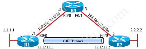
Basic interface configuration
| R1 interface e0/0 ip address 192.168.13.1 255.255.255.0 no shut interface loopback0 ip address 1.1.1.1 255.255.255.255 |
R2 interface e0/0 ip address 192.168.23.2 255.255.255.0 no shut interface loopback0 ip address 2.2.2.2 255.255.255.255 |
R3 interface e0/0 ip address 192.168.13.3 255.255.255.0 no shut interface e0/1 ip address 192.168.23.3 255.255.255.0 no shut |
Then configure GRE Tunnel
| R1 interface tunnel0 ip address 12.12.12.1 255.255.255.252 tunnel mode gre ip //this command can be ignored tunnel source 192.168.13.1 tunnel destination 192.168.23.2 |
R2 interface tunnel0 ip address 12.12.12.2 255.255.255.252 tunnel mode gre ip //this command can be ignored tunnel source 192.168.23.2 tunnel destination 192.168.13.1 |
In the first two commands (“interface tunnel …” and “ip address …”), we enter interface tunnel mode and configure IP addresses of the GRE tunnel interfaces in the same subnet (12.12.12.0/30) so that we don’t have to specific any routing protocol for routing between them. If we want to use two IP addresses in different subnet (like in the Internet) then we have to guarantee they know how to reach each other (via any routing protocol).
The next command “tunnel mode gre ip” is in fact not necessary as this is the default setting. We just want to show you this command and let you know that we are configuring a traditional point-to-point GRE. There are other GRE modes like “tunnel mode gre multipoint” used in DMVPN (mentioned in DMVPN tutorial).
Next we have to specify the tunnel source and tunnel destination with “tunnel source …” and “tunnel destination” commands. For “tunnel source” command, we can either specify the interface (for exampel “tunnel source e0/0”) or the IP address of the interface.
After above configuration, we will see a message:
| *Apr 27 02:45:55.653: %LINEPROTO-5-UPDOWN: Line protocol on Interface Tunnel0, changed state to down |
Verify with the “show ip interface brief” command:
R1#show ip interface brief
Interface                  IP-Address      OK? Method Status                Protocol
Ethernet0/0                192.168.13.1    YES manual up                    up
Ethernet0/1                unassigned      YES unset  administratively down down
Ethernet0/2                unassigned      YES unset  administratively down down
Ethernet0/3                unassigned      YES unset  administratively down down
Loopback0                  1.1.1.1         YES manual up                    up
Tunnel0                    12.12.12.1      YES manual up                    down
That means only Layer 1 of the tunnel is up, Layer 2 of the tunnel is still down (we usually call it “up/down” state). In order to make a Point-to-Point GRE Tunnel interface in up/up state, two requirements must be met:
+ A valid tunnel source (which is in up/up state and has an IP address configured on it) and tunnel destination must be configured
+ A valid tunnel destination is one which is routable. However, it does not have to be reachable.
In our case the first requirement is done because we used Ethernet0/0 as the tunnel source. It had an IP address and is in up/up state.
But the second requirement is missing as R1 does not know how to reach the tunnel destination 192.168.23.2. Therefore we have to instruct R1 how to reach 192.168.23.2. We can use any routing protocols (like RIP, OSPF or EIGRP) but here we only define a static route:
| R1(config)#ip route 192.168.23.0 255.255.255.0 192.168.13.3 |
This static route means “send all packets destined to 192.168.23.0/24 through 192.168.13.3”.
Now the tunnel on R1 is brought up without waiting for the configuration on R2.
| R1# *Apr 27 20:12:14.785: %LINEPROTO-5-UPDOWN: Line protocol on Interface Tunnel0, changed state to up |
Another notice is the tunnel source of R1 is also the tunnel destination of R2 and the tunnel destination of R1 is also the tunnel source of R2. The source & destination addresses of the tunnel are NOT the IP addresses of the tunnel interfaces themselves.
Finally we configure routing for two routers. In this lab we only configure a static route on each router to instruct the router to send which packet to the tunnel. Here we instruct R1 to send all traffic destined to 2.0.0.0/8 network through the tunnel (with the next hop of 12.12.12.2).
| R1(config)#ip route 2.0.0.0 255.0.0.0 12.12.12.2 |
If you don’t want to route the whole 2.0.0.0/8 network to the tunnel then you can instruct “ip route 2.2.2.2 255.255.255.255 12.12.12.2” on R1 instead.
That’s all for the configuration on R1. Let’s do the same thing on R2:
| R2(config)#ip route 192.168.13.0 255.255.255.0 192.168.23.3 R2(config)#ip route 1.0.0.0 255.0.0.0 12.12.12.1 |
And the tunnel interface on R2 comes up in a few seconds!
Now we can ping to 2.2.2.2 from R1:
| R1#ping 2.2.2.2 Type escape sequence to abort. Sending 5, 100-byte ICMP Echos to 2.2.2.2, timeout is 2 seconds: !!!!! |
This is the end of this tutorial. But we wish to test more about the “up/down” state of p2p GRE Tunnel which is described in this link: https://www.cisco.com/c/en/us/support/docs/ip/generic-routing-encapsulation-gre/118361-technote-gre-00.pdf
| “Under normal circumstances, there are only three reasons for a GRE tunnel to be in the up/down state: + There is no route, which includes the default route, to the tunnel destination address. + The interface that anchors the tunnel source is down. + The route to the tunnel destination address is through the tunnel itself, which results in recursion” |
We have already tested the first reason when the tunnel interface on R1 is in up/down state when no routing is configured to reach 192.168.13.3.
For the second reason, we will shutdown E0/0 of R1 to see the effect:
| R1(config)#interface e0/0 R1(config)# shutdown *Apr 27 04:57:52.325: %LINK-5-CHANGED: Interface Ethernet0/0, changed state to administratively down R1(config-if)# *Apr 27 04:57:53.330: %LINEPROTO-5-UPDOWN: Line protocol on Interface Ethernet0/0, changed state to down R1(config-if)# *Apr 27 04:58:00.410: %LINEPROTO-5-UPDOWN: Line protocol on Interface Tunnel0, changed state to down |
-> Tunnel’s line protocol goes down. Now we turn it on again to test the third reason.
R1(config)#interface e0/0
R1(config)# no shutdown
For testing the last reason we have to route the tunnel destination (192.168.23.0/24) through the tunnel itself (12.12.12.2) to create a recursion:
R1(config)#no ip route 192.168.23.0 255.255.255.0 192.168.13.3
R1(config)#ip route 192.168.23.0 255.255.255.0 12.12.12.2
We will see tunnel 0 is still in “up/down” state.
Note about tunnel state: A tunnel interface is in up/down state right after we create it (with the “interface tunnel <tunnel-number>” command). We cannot put it into down/down state, even if we shut down the source interface. We can only put it into “administratively down/down” by shutting down the tunnel itself. The tunnel interface does not change its state when we change/configure the other end of the tunnel.
Note: The tunnel connection does not get down when the MTUs on two sides are mismatched.


@abdullahi youre going to have to study very hard .
I am also so close to the deadline and only have 2 months study.
look up youtube videos for packet tracers and youll find some good ones. use cisco for the packet tracers as well as O’Reilly. Hope this helps
Thanks 9TUT such an amazing lab to practise..
Gracias por el tutorial, sirve para desempolvar los conocimientos de cisco. Exitos desde El Salvador.