CCNA – Frame Relay
Note: If you are not sure about Frame Relay, please read our Frame Relay Tutorial.
Question 1
Explanation
The PVC STATUS displays the status of the PVC. The DCE device creates and sends the report to the DTE devices. There are 4 statuses:
+ ACTIVE: the PVC is operational and can transmit data
+ INACTIVE: the connection from the local router to the switch is working, but the connection to the remote router is not available
+ DELETED: the PVC is not present and no LMI information is being received from the Frame Relay switch
+ STATIC: the Local Management Interface (LMI) mechanism on the interface is disabled (by using the “no keepalive” command). This status is rarely seen so it is ignored in some books.
Question 2
Explanation
The “show frame-relay map” command displays the current map entries and information about the connections, including encapsulation type.
You can check Table 33 in the following link: http://www.cisco.com/en/US/docs/ios/12_2/wan/command/reference/wrffr4.html#wp1029343
It clearly states there is a Field which can be Cisco or IETF, which “indicates the encapsulation type for this map”. We quote that Table 33 here for your quick reference (you will see what we want to imply in bold):
| Field | Description |
| Serial 1 (administratively down) | Identifies a Frame Relay interface and its status (up or down). |
| ip 131.108.177.177 | Destination IP address. |
| dlci 177 (0xB1,0x2C10) | DLCI that identifies the logical connection being used to reach this interface. This value is displayed in three ways: its decimal value (177), its hexadecimal value (0xB1), and its value as it would appear on the wire (0x2C10). |
| static | Indicates whether this is a static or dynamic entry. |
| CISCO | Indicates the encapsulation type for this map; either CISCO or IETF. |
| TCP/IP Header Compression (inherited), passive (inherited) | Indicates whether the TCP/IP header compression characteristics were inherited from the interface or were explicitly configured for the IP map. |
The “show frame-relay lmi” gives us information about the LMI encapsulation type used by the Frame Relay interface, which can be ANSI, CISCO or Q933a. Therefore it is not what the question requires (CISCO or IETF).
Question 3
Explanation
DLCI stands for Data Link Connection Identifier. DLCI values are used on Frame Relay interfaces to distinguish between different virtual circuits. DLCIs have local significance because the identifier references the point between the local router and the local Frame Relay switch to which the DLCI is connected.
Question 4
Explanation
First we should grasp the concept of BECN & FECN through an example:
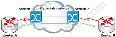
Suppose Router A wants to send data to Router B through a Frame Relay network. If the network is congested, Switch 1 (a DCE device) will set the FECN bit value of that frame to 1, indicating that frame experienced congestion in the path from source to destination. This frame is forwarded to Switch 2 and to Router B (with the FECN bit = 1).
Switch 1 knows that the network is congesting so it also sends frames back to Router A with BECN bit set to 1 to inform that path through the network is congested.
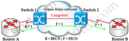
In general, BECN is used on frames traveling away from the congested area to warn source devices that congestion has occurred on that path while FECN is used to alert receiving devices if the frame experiences congestion.
BECN also informs the transmitting devices to slow down the traffic a bit until the network returns to normal state.
The question asks “which output value indicates to the local router that traffic sent to the corporate site is experiencing congestion” which means it asks about the returned parameter which indicates congestion -> BECN.
Question 5
Explanation
Committed information rate (CIR): The minimum guaranteed data transfer rate agreed to by the Frame Relay switch. Frames that are sent in excess of the CIR are marked as discard eligible (DE) which means they can be dropped if the congestion occurs within the Frame Relay network.
Note: In the Frame Relay frame format, there is a bit called Discard eligible (DE) bit that is used to identify frames that are first to be dropped when the CIR is exceeded.
Question 6
Question 7
Explanation
First we have to say this is an unclear question and it is wrong. The “frame-relay map ip” statement is correct thus none of the four answers above is correct. But we guess there is a typo in the output. Maybe the “ip address 172.16.100.2 255.255.0.0” command should be “ip address 172.16.100.1 255.255.0.0”. That makes answer C correct.
Question 8
Explanation
The term dynamic indicates that the DLCI number and the remote router IP address 172.16.3.1 are learned via the Inverse ARP process.
Inverse ARP is a technique by which dynamic mappings are constructed in a network, allowing a device such as a router to locate the logical network address and associate it with a permanent virtual circuit (PVC).
Question 9
Explanation
Local Management Interface (LMI) is a signaling standard protocol used between your router (DTE) and the first Frame Relay switch. From the output we learn this interface is sending and receiving LMI messages -> Frame Relay is being used.
Question 10
Explanation
The command frame-relay map ip 10.121.16.8 102 broadcast means to mapping the distal IP 10.121.16.8 102to the local DLCI 102. When the “broadcast” keyword is included, it turns Frame Relay network as a broadcast network, which can forward broadcasts.