
OSI Model Tutorial
Welcome to the most basic tutorial for networker! Understanding about OSI model is one of the most important tools to help you grasp how networking devices like router, switch, PC… work.
Let’s take an example in our real life to demonstrate the OSI model. Maybe you have ever sent a mail to your friend, right? To do it, you have to follow these steps:
1. Write your letter
2. Insert it into an envelope
3. Write information about sender and receiver on that envelope
4. Stamp it
5. Go to the post office and drop it into a mail inbox
From the example above, I want to imply we have to go through some steps in a specific order to complete a task. It is also applied for two PCs to communicate with each other. They have to use a predefined model, named OSI, to complete each step. There are 7 steps in this model as listed below:
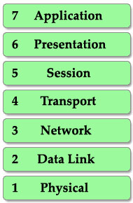
This is also the well-known table of the OSI model so you must take time to learn by heart. A popular way to remember this table is to create a fun sentence with the first letters of each layer. For example: All People Seem To Need Data Processing or a more funny sentence sorted from layer 1 to layer 7: Please Do Not Throw Sausage Pizza Away.
There are two notices about this table:
1. First, the table is arranged from top to bottom (numbering from 7 to 1). Each step is called a “layer” so we have 7 layers (maybe we usually call them “layers” to make them more… technical ^^).
When a device wants to send information to another one, its data must go from top to bottom layer. But when a device receives this information, it must go from bottom to top to “decapsulate” it. In fact, the reverse action at the other end is very natural in our life. It is very similar when two people communicate via mail. First, the writer must write the letter, insert it into an envelope while the receiver must first open the envelope and then read the mail. The picture below shows the whole process of sending and receiving information.
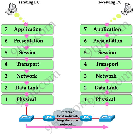
Note: The OSI model layers are often referred to by number than by name (for example, we refer saying “layer 3” to “network layer”) so you should learn the number of each layer as well.
2. When the information goes down through layers (from top to bottom), a header is added to it. This is called “encapsulation” because it is like wrapping an object in a capsule. Each header can be understood only by the corresponding layer at the receiving side. Other layers only see that layer’s header as a part of data.
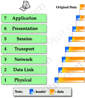
At the receiving side, corresponding header is stripped off in the same layer it was attached. This process is called “decapsulation”.
Understand each layer
Layer 7 – Application layer
This is the closest layer to the end user. It provides the interface between the applications we use and the underlying layers. But notice that the programs you are using (like a web browser – IE, Firefox or Opera…) do not belong to Application layer. Telnet, FTP, email client (SMTP), HyperText Transfer Protocol (HTTP) are examples of Application layer.
Layer 6 – Presentation layer
This layer ensures the presentation of data, that the communications passing through are in the appropriate form for the recipient. In general, it acts as a translator of the network. For example, you want to send an email and the Presentation will format your data into email format. Or you want to send photos to your friend, the Presentation layer will format your data into GIF, JPG or PNG… format.
Layer 5 – Session layer
Layer 5 establishes, maintains and ends communication with the receiving device.
Layer 4 – Transport layer
This layer maintains flow control of data and provides for error checking and recovery of data between the devices. The most common example of Transport layer is Transmission Control Protocol (TCP) and User Datagram Protocol (UDP).
Layer 3 – Network layer
This layer provides logical addresses which routers will use to determine the path to the destination. In most cases, the logic addresses here means the IP addresses (including source & destination IP addresses).
Layer 2 – Data Link Layer
The Data Link layer formats the message into a data frame, and adds a header containing the hardware destination and source address to it. This header is responsible for finding the next destination device on a local network.
Notice that layer 3 is responsible for finding the path to the last destination (network) but it doesn’t care about who will be the next receiver. It is the Layer 2 that helps data to reach the next destination.
This layer is subdivide into 2 sub-layers: logical link control (LLC) and media access control (MAC).
The LLC functions include:
+ Managing frames to upper and lower layers
+ Error Control
+ Flow control
The MAC sublayer carries the physical address of each device on the network. This address is more commonly called a device’s MAC address. MAC address is a 48 bits address which is burned into the NIC card on the device by its manufacturer.
Layer 1 – Physical layer
The Physical Layer defines the physical characteristics of the network such as connections, voltage levels and timing.
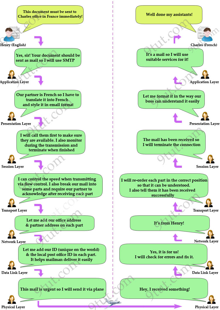
To help you remember the functions of each layer more easily, I created a fun story in which Henry (English) wants to send a document to Charles (French) to demonstrate how the OSI model works.
Lastly, I summarize all the important functions of each layer in the table below (please remember them, they are very important knowledge you need to know about OSI model):
| Layer | Description | Popular Protocols | Protocol Data Unit | Devices operate in this layer |
| Application | + User interface | HTTP, FTP, TFTP, Telnet, SNMP, DNS… | Data | |
| Presentation | + Data representation, encryption & decryption |
+ Video (WMV, AVI…) |
Data | |
| Session | + Set up, monitor & terminate the connection session | + SQL, RPC, NETBIOS names… | Data | |
| Transport | + Flow control (Buffering, Windowing, Congestion Avoidance) helps prevent the loss of segments on the network and the need for retransmission | + TCP (Connection-Oriented, reliable) + UDP (Connectionless, unreliable) |
Segment | |
| Network | + Path determination + Source & Destination logical addresses |
+ IP + IPX + AppleTalk |
Packet/Datagram | Router |
| Data Link |
+ Physical addresses Includes 2 layers: |
+ LAN + WAN (HDLC, PPP, Frame Relay…) |
Frame | Switch, Bridge |
| Physical |
Encodes and transmits data bits + Electric signals |
+ FDDI, Ethernet | Bit (0, 1) | Hub, Repeater… |
Note: In fact, OSI is just a theoretical model of networking. The practical model used in modern networks is the TCP/IP model. You may think “Hm, it’s just theoretic and has no use in real life! I don’t care!” but believe me, you will use this model more often than the TCP/IP model so take time to grasp it, you will not regret – I promise :)


Thank you
Thanks
super sir
Thank you sir/ma’am
Very informative, thank you.
Gracias por la información