Frame Relay Tutorial
Note: Frame Relay is no longer a topic in CCNAv3 200-125 exam.
Let’s start this article with the question: Why do we need Frame Relay?
Let’s take a simple example. Suppose you are working in a big company and your company has just expanded to two new locations. The main site is connected to two branch offices, named Branch 1 & Branch 2 and your boss wants these two branches can communicate with the main site. The most simple solution is to connect them directly (called a leased line) as shown below:
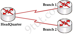
To connect to these two branches, the main site router, HeadQuarter, requires two serial interfaces which a router can provide. But what happens when the company expands to 10 branches, 50 branches? For each point-to-point line, HeadQuarter needs a separate physical serial interface (and maybe a separate CSU/DSU if it is not integrated into the WAN card). As you can imagine, it will need many routers with many interfaces and lots of rack space for the routers and CSU/DSUs. Maybe we should use another solution for this problem? Luckily, Frame Relay can do it!
By using Frame Relay we only need one serial interface at the HeadQuarter to connect to all branches. This is also true when we expand to 10 or 50 branches. Moreover, the cost is much lesser than using leased-lines.
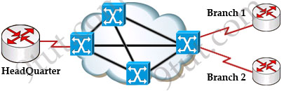
Frame Relay is a high-performance WAN protocol that operates at the physical and data link layers of the OSI reference model. It offers lower-cost data transfer when compared to typical point-to-point applications, by using virtual connections within the frame relay network and by combining those connections into a single physical connection at each location. Frame relay providers use a frame relay switch to route the data on each virtual circuit to the appropriate destination.
Maybe these terminologies of Frame Relay are difficult to understand so we will explain them in more detail in this article.
DCE & DTE
The first concept in Frame Relay you must grasp is about DTE & DCE:
+ Data terminal equipment (DTE), which is actually the user device and the logical Frame-relay end-system
+ Data communication equipment (DCE, also called data circuit-terminating equipment), which consists of modem and packet switch
In general, the routers are considered DTE, and the Frame Relay switches are DCE. The purpose of DCE equipment is to provide clocking and switching services in a network. In our example, HeadQuarter, Branch 1 & Branch 2 are DTEs while Frame Relay switches are DCEs.
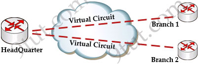
Virtual Circuits
The logical connection through the Frame Relay network between two DTEs is called a virtual circuit (VC). The term “virtual” here means that the two DTEs are not connected directly but through a network. For example, the HeadQuarter & Branch 1 (or Branch 2) can communicate with each other as if they were directly connected but in fact they are connected through a Frame Relay network with many Frame Relay switches between them.
There are two types of VCs
+ switched virtual circuits (SVCs): are temporary connections that are only used when there is sporadic data transfer between DTE devices across the Frame Relay network. SVC is set up dynamically when needed. SVC connections require call setup and termination for each connection.
+ permanent virtual circuits (PVCs): A predefined VC. A PVC can be equated to a leased line in concept.
Nowadays most service providers offer PVC service only to save additional costs for signaling and billing procedures.