
InterVLAN Routing Tutorial
In the previous VLAN tutorial we learned how to use VLAN to segment the network and create “logical” broadcast domains. In this tutorial we will learn about InterVLAN Routing.
What is InterVLAN routing?
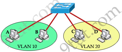
As we learned, devices within a VLAN can communicate with each other without the need of Layer 3 routing. But devices in separate VLANs require a Layer 3 routing device to communicate with one another. For example, in the topology below host A and B can communicate with each other without a router in the same VLAN 10; host C and D can communicate in the same VLAN 20. But host A can’t communicate with host C or D because they are in different VLANs.
To allow hosts in different VLANs communicate with each other, we need a Layer 3 device (like a router) for routing:
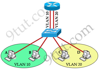
The routing traffic from one VLAN to another VLAN is called InterVLAN routing.
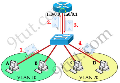
Now host A can communicate with host C or D easily. Now let’s see how the traffic is sent from host A to host D. First, host A knows the destination host is in a different VLAN so it sends traffic to its default gateway (on the router) through the switch. The switch tags the frame as originating on VLAN 10 and forwards to the router. In turn, the router makes routing decision from VLAN 10 to VLAN 20 and sends back that traffic to the switch, where it is forwarded out to host D.
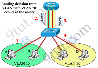
Notice that the routing decision to another VLAN is done by the router, not the switch. When frames leave the router (step 3 in the picture above), they are tagged with VLAN 20.
Also notice that receiving ends (host A & D in this case) are unaware of any VLAN information. Switch attaches VLAN information when receiving frames from host A and removes VLAN information before forwarding to host D.
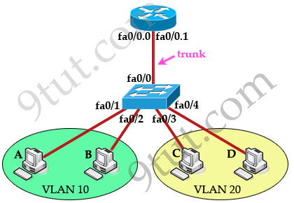
But there is one disadvantage in the topology above: for each VLAN we need a physical connection from the router to the switch but in practical, the interfaces of the router are very limited. To overcome this problem, we can create many logical interfaces in one physical interface. For example from a physical interface fa0/0 we can create many sub-interfaces like fa0/0.0, fa0/0.1 … Now this router is often called “router on a stick” (maybe because there is only one physical link connecting from router so it looks like a router on a stick ^^)
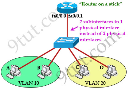
The router treats each sub-interface as a separate physical interface in routing decisions -> data can be sent and received in the same physical interface (but different sub-interfaces) without being dropped by the split-horizon rule in the case you want to send routing updates through the router from one VLAN to another.
Configuring InterVLAN routing
Now you understand how InterVLAN works. To accomplish InterVLAN routing, some configuration must be implemented on both router and switch. Let’s see what actions need to be completed when we want to configure InterVLAN in “router on a stick” model using the above topology.
+ The switch port connected to the router interface must be configured as trunk port.
+ The router sub-interfaces must be running a trunking protocol. Two popular trunking protocols in CCNA are 802.1q (open standard) and InterSwitch Link (ISL, a Cisco propriety protocol).
+ Set IP address on each sub-interface.
To help you understand more clearly about InterVLAN, the main configuration of router & switch are shown below:
Configure trunk port on switch:
Switch(config)#interface f0/0
Switch(config-if)#no shutdown
Switch(config-if)#switchport mode trunk
Create sub-interfaces, set 802.1Q trunking protocol and ip address on each sub-interface
Router(config)#interface f0/0
Router(config-if)#no shutdown
(Note: The main interface f0/0 doesn’t need an IP address but it must be turned on)
Router(config)#interface f0/0.0
Router(config-subif)#encapsulation dot1q 10
Router(config-subif)#ip address 192.168.1.1 255.255.255.0
Router(config-subif)#interface f0/0.1
Router(config-subif)#encapsulation dot1q 20
Router(config-subif)#ip address 192.168.2.1 255.255.255.0
(Note: In the “encapsulation dot1q 10” command, 10 is the VLAN ID this interface operates in)
I also list the full configuration of the above topology for your reference:
Configure VLAN
Switch(config)#vlan 10
Switch(config-vlan)#name SALES
Switch(config-vlan)#vlan 20
Switch(config-vlan)#name TECH
Set ports to access mode & assign ports to VLAN
Switch(config)#interface range fa0/1-2
Switch(config-if)#no shutdown
Switch(config-if)# switchport mode access
Switch(config-if)# switchport access vlan 10
Switch(config-if)#interface range fa0/3-4
Switch(config-if)#no shutdown
Switch(config-if)#switchport mode access
Switch(config-if)# switchport access vlan 20
In practical, we often use a Layer 3 switch instead of a switch and a “router on the stick”, this helps reduce the complexity of the topology and cost.
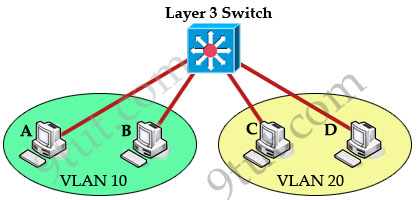
Note: With this topology, we don’t need to use a trunking protocol and the “switchport mode trunk” command. The full configuration of Layer 3 switch is listed below:
Switch configuration
|
ip routing interface Vlan10 |
And on hosts just assign IP addresses and default gateways (to the corresponding interface VLANs) -> hosts in different VLANs can communicate.
In summary, InterVLAN routing is used to permit devices on separate VLANs to communicate. In this tutorial you need to remember these important terms:
+ Router-on-a-stick: single physical interface routes traffic between multiple VLANs on a network.
+ Subinterfaces are multiple virtual interfaces, associated with one physical interface. These subinterfaces are configured in software on a router that is independently configured with an IP address and VLAN assignment.


Useful articles. Thanks a lot !!!
Great !
Excellent articles.
cool topic
What do you guys use to create your network diagram pictures? The icons and colors are great