CCNA – Troubleshooting 1
Here you will find answers to Trouble Shooting Questions (Part 1)
Question 1:
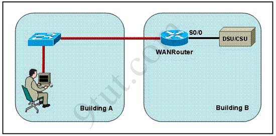
Refer to the exhibit. The network administrator is in a campus building distant from Building B. WANRouter is hosting a newly installed WAN link on interface S0/0. The new link is not functioning and the administrator needs to determine if the correct cable has been attached to the S0/0 interface. How can the administrator accurately verify the correct cable type on S0/0 in the most efficient manner?
A. Telnet to WANRouter and execute the command show interfaces S0/0
B. Telnet to WANRouter and execute the command show processes S0/0
C. Telnet to WANRouter and execute the command show running-configuration
D. Telnet to WANRouter and execute the command show controller S0/0
E. Physically examine the cable between WANRouter S0/0 and the DCE.
F. Establish a console session on WANRouter and execute the command show interfaces S0/0
Answer: D
Explanation:
The show controller command displays the information about the physical interface itself and the type of serial cable plugged into a serial port. In this case, it should be a DTE cable that plugs into a type of data service unit (DSU).
For your understanding, below is the output of this command:
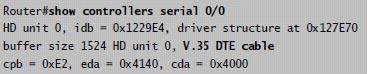
From the output, we notice that serial 0/0 has a DTE cable and would get its clocking from the DSU.
Question 2:
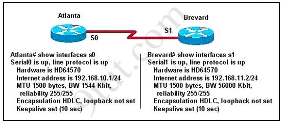
Two routers named Atlanta and Brevard are connected by their serial interfaces as shown in the exhibit, but there is no data connectivity between them. The Atlanta router is known to have a correct configuration. Given the partial configurations shown in the exhibit, what is the problem on the Brevard router that is causing the lack of connectivity?
A. A loopback is not set
B. The IP address is incorrect.
C. The subnet mask is incorrect.
D. The serial line encapsulations are incompatible.
E. The maximum transmission unit (MTU) size is too large.
F. The bandwidth setting is incompatible with the connected interface.
Answer: B
Question 3:
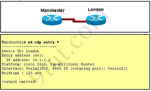
Refer to the exhibit. The two exhibited devices are the only Cisco devices on the network. The serial network between the two devices has a mask of 255.255.255.252. Given the output that is shown, what three statements are true of these devices? (Choose three)
A. The Manchester serial address is 10.1.1.1.
B. The Manchester serial address is 10.1.1.2.
C. The London router is a Cisco 2610.
D. The Manchester router is a Cisco 2610.
E. The CDP information was received on port Serial0/0 of the Manchester router.
F. The CDP information was sent by port Serial0/0 of the London router.
Answer: A C E
Explanation:
From the output, we learn that the IP address of the neighbor router is 10.1.1.2 and the question stated that the subnet mask of the network between two router is 255.255.255.252. Therefore there are only 2 available hosts in this network (22 – 2 = 2). So we can deduce the ip address (of the serial interface) of Manchester router is 10.1.1.1 -> A is correct
The flatform of the neighbor router is cisco 2610, as shown in the output -> C is correct
Maybe the most difficult choice of this question is the answer E or F. Please notice that “Interface” refers to the local port on the local router, in this case it is the port of Manchester router, and “Port ID (outgoing port)” refers to the port on the neighbor router -> E is correct.
Question 4:
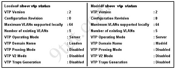
A network administrator has configured two switches, named London and Madrid, to use VTP. However, the switches are not sharing VTP messages. Given the command output shown in the graphic, why are these switches not sharing VTP messages?
A. The VTP version is not correctly configured.
B. The VTP operating mode is not correctly configured.
C. The VTP domain name is not correctly configured.
D. VTP pruning mode is disabled.
E. VTP V2 mode is disabled.
F. VTP traps generation is disabled.
Answer: C
Explanation
In the exhibit, the Domain Names of 2 switches are mismatched (one is “London” and the other is “Madrid”) so these switches do not share VTP messages -> The VTP domain name is not correctly configured. Notice that the Domain Names should be the same on both switches to share VTP messages.
Question 5:
The network shown in the diagram is experiencing connectivity problems. Which of the following will correct the problems? (Choose two.)
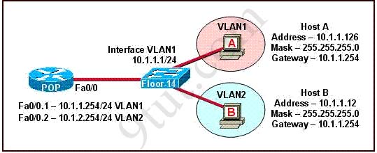
A. Configure the gateway on Host A as 10.1.1.1.
B. Configure the gateway on Host B as 10.1.2.254.
C. Configure the IP address of Host A as 10.1.2.2.
D. Configure the IP address of Host B as 10.1.2.2.
E. Configure the masks on both hosts to be 255.255.255.224.
F. Configure the masks on both hosts to be 255.255.255.240.
Answer: B D
Question 6:
Refer to the exhibit:
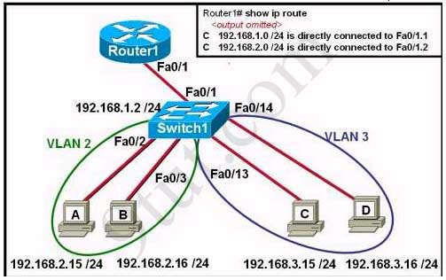
The network administrator has created a new VLAN on Switch1 and added host C and host D. The administrator has properly configured switch interfaces FastEthernet0/13 through FastEthernet0/24 to be members of the new VLAN. However, after the network administrator completed the configuration, host A could communicate with host B, but host A could not communicate with host C or host D. Which commands are required to resolve this problem?
A. Router(config)# interface fastethernet 0/1.3
Router(config-if)# encapsulation dot1q 3
Router(config-if)# ip address 192.168.3.1 255.255.255.0
B. Router(config)# router rip
Router(config-router)# network 192.168.1.0
Router(config-router)# network 192.168.2.0
Router(config-router)# network 192.168.3.0
C. Switch1# vlan database
Switch1(vlan)# vtp v2-mode
Switch1(vlan)# vtp domain cisco
Switch1(vlan)# vtp server
D. Switch1(config)# interface fastethernet 0/1
Switch1(config-if)# switchport mode trunk
Switch1(config-if)# switchport trunk encapsulation isl
Answers: A
Question 7:
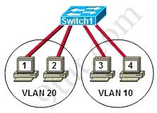
Refer to the exhibit. Hosts on the same VLAN can communicate with each other but are unable to communicate with hosts on different VLANs. What is needed to allow communication between VLANs?
A. a switch with a trunk link that is configured between the switches
B. a router with an IP address on the physical interface that is connected to the switch
C. a switch with an access link that is configured between the switches
D. a router with subinterfaces configured on the physical interface that is connected to the switch
Answer: D
Question 8:
The show interfaces serial 0/0 command resulted in the output shown in the graphic. What are possible causes for this interface status? (Choose three)
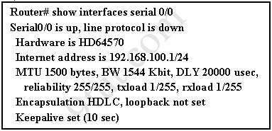
A. The interface is shut down.
B. No keepalive messages are received.
C. The clockrate is not set.
D. No loopback address is set.
E. No cable is attached to the interface.
F. There is a mismatch in the encapsulation type.
Answer: B C F
Question 9:
While troubleshooting a connectivity issue from a PC you obtain the following information:
Local PC IP address: 10.0.0.35/24
Default Gateway: 10.0.0.1
Remote Sever: 10.5.75.250/24
You then conduct the following tests from the local PC:
Ping 127.0.0.1 – Successful
Ping 10.0.0.35 – Successful
Ping 10.0.0.1 – Unsuccessful
Ping 10.5.75.250 – Unsuccessful
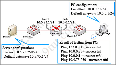
What is the underlying cause of this problem?
A. A remote physical layer problem exists.
B. The host NIC is not functioning.
C. TCP/IP has not been correctly installed on the host.
D. A local physical layer problem exists.
Answer: D