
Frame Relay Tutorial
In this part we will continue to discuss about other important Frame Relay parameters
DLCI
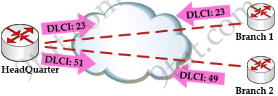
Although the above picture shows two VCs from the HeadQuarter but do you remember that the HeadQuarter only has only one serial interface? So how can it know which branch it should send the frame to?
Frame-relay uses data-link connection identifiers (DLCIs) to build up logical circuits. The identifiers have local meaning only, that means that their values are unique per router, but not necessarily in the other routers. For example, there is only one DLCI of 23 representing for the connection from HeadQuarter to Branch 1 and only one DLCI of 51 from HeadQuarter to Branch 2. Branch 1 can use the same DLCI of 23 to represent the connection from it to HeadQuarter. Of course it can use other DLCIs as well because DLCIs are just local significant.
By including a DLCI number in the Frame Relay header, HeadQuarter can communicate with both Branch 1 and Branch 2 over the same physical circuit.
DLCI values typically are assigned by the Frame Relay service provider (for example, the telephone company). In Frame Relay, DLCI is a 10-bit field.
Before DLCI can be used to route traffic, it must be associated with the IP address of its remote router. For example, suppose that:
+ HeadQuarter’s IP address is 9.9.9.9
+ Branch 1’s IP address is 1.1.1.1
+ Branch 2’s IP address is 2.2.2.2
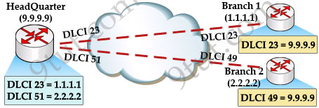
Then the HeadQuarter will need to map Branch 1 IP address to DLCI 23 & map Branch 2 IP address to DLCI 51. After that it can encapsulate data inside a Frame Relay frame with an appropriate DLCI number and send to the destination. The mapping of DLCIs to Layer 3 addresses can be handled manually or dynamically.
* Manually (static): the administrators can statically assign a DLCI to the remote IP address by the following statement:
Router(config-if)#frame-relay map protocol dlci [broadcast]
For example HeadQuarter can assign DLCIs of 23 & 51 to Branch 1 & Branch 2 with these commands:
HeadQuarter(config-if)#frame-relay map ip 1.1.1.1 23 broadcast
HeadQuarter(config-if)#frame-relay map ip 2.2.2.2 51 broadcast
We should use the “broadcast” keyword here because by default split-horizon will prevent routing updates from being sent back on the same interface it received. For example, if Branch 1 sends an update to HeadQuarter then HeadQuarter can’t send that update to Branch 2 because they are received and sent on the same interface. By using the “broadcast” keyword, we are telling the HeadQuarter to send a copy of any broadcast or multicast packet received on that interface to the virtual circuit specified by the DLCI value in the “frame-relay map” statement. In fact the copied packet will be sent via unicast (not broadcast) so sometimes it is called “pseudo-broadcast”.
Note: “frame-relay interface-dlci” command can be used to statically assign (bind) a DLCI number to a physical interface.
Note: In fact, we need to run a routing protocol (like OSPF, EIGRP or RIP…) to make different networks see each other
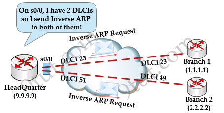
* Dynamic: the router can send an Inverse ARP Request to the other end of the PVC for its Layer 3 address. In short, Inverse ARP will attempt to learn its neighboring devices IP addresses and automatically create a dynamic map table. By default, physical interfaces have Inverse ARP enabled.
We will take an example of how Inverse ARP works with the topology above. At the beginning, all routers are not configured with static mapping and HeadQuarter has not learned the IP addresses of Branch 1 & 2 yet. It only has 2 DLCI values on s0/0 interface (23 & 51). Now it needs to find out who are attached to these DLCIs so it sends an Inverse ARP Request on s0/0 interface. Notice that the router will send Inverse ARP Request out on every DLCI associated with the interface.
In the Inverse ARP Request, HeadQuarter also includes its IP 9.9.9.9. When Branch 1 & 2 receive this request, they send back an Inverse ARP Reply with their own IP addresses.
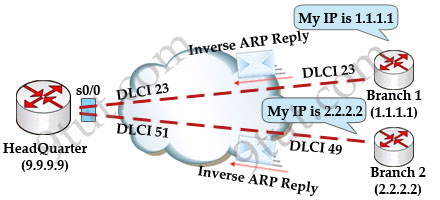
Now all the routers have a pair of DLCI & IP address of the router at the other end so data can be forwarded to the right destination.
In this example you can see that each router has a DLCI first (Layer 2) and it needs to find out the IP address (Layer 3). This process is opposite of the ARP process (ARP translates Layer 3 address to Layer 2 address) so it is called Inverse ARP.
After the Inverse ARP process completes, we can use the “show frame-relay map” to check. The word “dynamic” indicates the mapping was learned through Inverse ARP (the output below is not related to the above topology):
![]()
By default, routers send Inverse ARP messages on all active DLCIs every 60 seconds.
Another thing you should notice is when you supply a static map (via “frame-relay map” command), Inverse ARP is automatically disabled for the specified protocol on the specified DLCI.


Thank you! This information is very hard to find on the Internet
Hello! How can I get to your office?
is frame relay topic is included in CCNA exam for 2023?
Frame Relay is no longer a topic in the current CCNA.
Excellent brief explanation. Consise and to-the-point.