
Basic Questions
Question 1
Question 2
Explanation
If the destination MAC address is not in the CAM table (unknown destination MAC address), the switch sends the frame out all other ports that are in the same VLAN as the received frame. This is called flooding. It does not flood the frame out the same port on which the frame was received.
Question 3
Question 4
Explanation
PoE monitoring and policing compares the power consumption on ports with the administrative maximum value (either a configured maximum value or the port’s default value). If the power consumption on a monitored port exceeds the administrative maximum value, the following actions occur:
+ A syslog message is issued.
+ The monitored port is shut down and error-disabled.
+ The allocated power is freed.
Question 5
Explanation
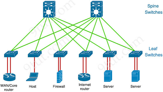
Spine-leaf architecture is typically deployed as two layers: spines (such as an aggregation layer), and leaves (such as an access layer). Spine-leaf topologies provide high-bandwidth, low-latency, nonblocking server-to-server connectivity.
Leaf (access) switches are what provide devices access to the fabric (the network of spine and leaf switches) and are typically deployed at the top of the rack. Generally, devices connect to the leaf switches. Devices can include servers, Layer 4-7 services (firewalls and load balancers), and WAN or Internet routers. Leaf switches do not connect to other leaf switches. In spine-and-leaf architecture, every leaf should connect to every spine in a full mesh.
Spine (aggregation) switches are used to connect to all leaf switches and are typically deployed at the end or middle of the row. Spine switches do not connect to other spine switches.
Question 6
Explanation
Whenever the physical transmission has problems, the receiving device might receive a frame whose bits have changed values. These frames do not pass the error detection logic as implemented in the FCS field in the Ethernet trailer. The receiving device discards the frame and counts it as some kind of input error. Cisco switches list this error as a CRC error. Cyclic redundancy check (CRC) is a term related to how the FCS math detects an error.
The “input errors” includes runts, giants, no buffer, CRC, frame, overrun, and ignored counts.
The output below show the interface counters with the “show interface s0/0/0” command:
Router#show interface s0/0/0
Serial0/0/0 is up, line protocol is up
  Hardware is M4T
  Description: Link to R2
  Internet address is 10.1.1.1/30
  MTU 1500 bytes, BW 1544 Kbit, DLY 20000 usec,
     reliability 255/255, txload 1/255, rxload 1/255
  --output omitted--
  5 minute output rate 0 bits/sec, 0 packets/sec
     268 packets input, 24889 bytes, 0 no buffer
     Received 0 broadcasts, 0 runts, 0 giants, 0 throttles
     0 input errors, 0 CRC, 0 frame, 0 overrun, 0 ignored, 0 abort
     251 packets output, 23498 bytes, 0 underruns
     0 output errors, 0 collisions, 0 interface resets
     0 output buffer failures, 0 output buffers swapped out
     0 carrier transitions     DCD=up  DSR=up  DTR=up  RTS=up  CTS=up
Question 7
Explanation
A late collision is defined as any collision that occurs after the first 512 bits (or 64th byte) of the frame have been transmitted. The usual possible causes are full-duplex/half-duplex mismatch, exceeded Ethernet cable length limits, or defective hardware such as incorrect cabling, non-compliant number of hubs in the network, or a bad NIC.
Late collisions should never occur in a properly designed Ethernet network. They usually occur when Ethernet cables are too long or when there are too many repeaters in the network.
Reference: https://www.cisco.com/en/US/docs/internetworking/troubleshooting/guide/tr1904.html
Question 8
Question 9
Question 10
Question 11
Question 12


Anyone having fresh dumps for 200-301 exam please send them to email {email not allowed}
Anyone having fresh dumps for 200-301 exam please send them to email motlamedipatirck48/gmail/com
are these current?